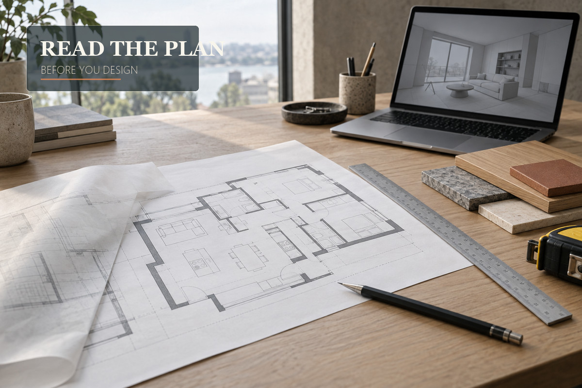
Read a floor plan in a structured sequence: verify the drawing conventions first, identify unmovable boundaries, test stated dimensions against actual furniture clearances, trace daily traffic routes, and catalog the vertical conditions the drawing leaves out. This disciplined approach translates two-dimensional architectural drawings into an actionable interior design brief.
While a floor plan clarifies space allocation, it cannot confirm on-site framing, structural capacity, building codes, or construction feasibility. Use the drawing to organize layout priorities and pinpoint spatial conflicts before engaging a field survey and consulting licensed trade professionals.
Start With the Legend, Direction, and Scale
Drawing interpretation starts with the title block and legend, which establish the rules governing every line and symbol on the sheet. Locate the drawing number, issue date, revision notes, north arrow, and graphic symbols. Because graphic standards differ across architects and drafting software, the sheet’s specific legend overrides generic symbol guides.
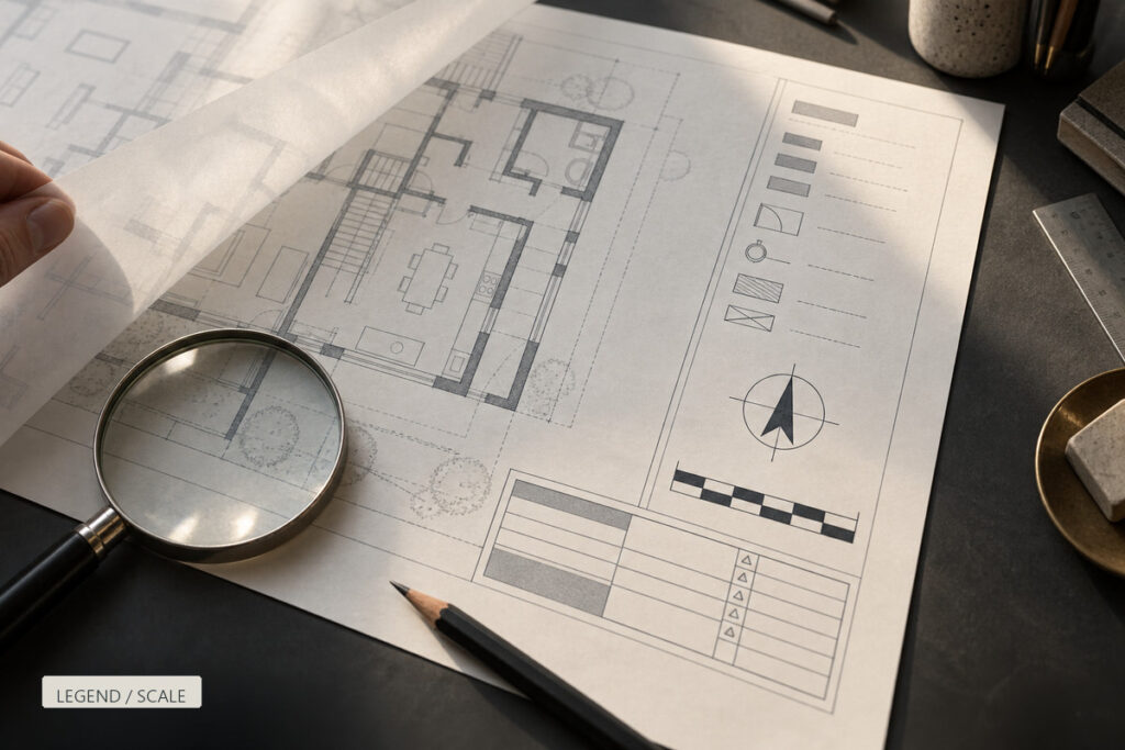
Scale defines how drawing units translate to the physical building, typically shown as an architectural ratio (such as 1/4 inch equals 1 foot or 1:50) alongside a graphic bar scale. When prints or PDF exports are scaled to fit paper sizes, numerical ratios distort, making the graphic scale bar essential for quick verification. Always prioritize written dimension callouts over visual estimation, noting any contradictory figures for physical verification on site.
Use the numbered markers on the annotated plan as a systematic review sequence:
- Check the title block, revision date, and stated scale.
- Confirm solar orientation from the north arrow.
- Distinguish exterior wall boundaries from interior partitions.
- Note door swing directions and window openings.
- Locate stairs, plumbing chases, and fixed cabinetry.
- Compare furniture footprints against necessary walking clearances.
- Trace primary travel routes between public and private rooms.
Read the Elements That Define the Space
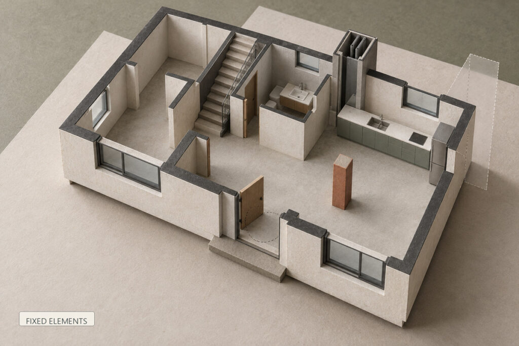
Analyze the building envelope and fixed architectural elements before considering decorative finishes or movable furniture. These fixed features determine the true usable volume of each room and expose structural constraints that simple room labels obscure.
Walls and Openings
Trace the exterior perimeter walls before evaluating interior room partitions. In architectural plans, wall lines represent horizontal section cuts taken at approximately 4 feet (1.2 meters) above the finished floor. Heavier line weights or double-line hatching indicate thicker assemblies, such as exterior cavity walls, plumbing chases, or sound-insulated partitions, rather than confirming structural load capacity. Mark any walls you wish to reconfigure so your architect or structural engineer can evaluate them against the framing plan.
Doors appear as a straight leaf with an operating arc showing the direction of swing. Verify which side holds the hinge jamb, where the door rests when fully open, and whether overlapping door paths create bottlenecks in tight corridors. Windows appear as wall breaks with parallel glass lines, though plan views rarely show sill heights, head heights, or casing profiles. Verify the project’s formal window and door schedule before adopting any standard interior door size as a fixed planning baseline, ensuring swings clear light switches and adjacent cabinetry.
Stairs and Fixed Fixtures
Stairs appear as a run of parallel tread lines accompanied by an arrow indicating travel direction, usually labeled UP or DN. Pay close attention to intermediate landings, turn directions, and the diagonal break line showing where the stair rises above the current floor plane. Because a two-dimensional plan flattens vertical space, it conceals overhead headroom constraints, sloped soffits, and usable volume beneath the stringers.
Fixed kitchen islands, bathroom vanities, shower enclosures, structural columns, and mechanical shafts reduce the open floor area available for everyday living. Treat these elements as immovable physical boundaries. Cross-reference them with interior elevations, reflected ceiling plans, and on-site rough-in photographs to verify that plumbing stacks or vent chases will not disrupt customized joinery.
Check Dimensions Against Furniture Use
Room dimensions provide meaningful guidance only when evaluated against finished wall surfaces, door clearance envelopes, and the physical space furniture requires in active use. A room that appears spacious on paper can quickly feel constrained once cabinet doors, chairs, and walking paths compete for the same square footage.
Usable Room Dimensions
To see how to read floor plan dimensions in an architectural drawing, follow dimension strings from the exterior inward. The outermost string records overall building boundaries, the intermediate string tracks structural centerlines and partition walls, and the innermost string measures wall returns, cabinetry recesses, and rough window openings. Always note whether numbers measure rough framing studs or finished drywall faces, as finish layers and baseboards shave valuable inches off usable room width.
Compile a checklist of vertical and recessed conditions that plan dimensions omit. Flat plans rarely indicate finished ceiling heights, dropped soffits, structural beam drops, window sill elevations, or changes in finished floor levels. While these architectural conditions do not alter measured floor area, they directly dictate maximum cabinet heights, drapery pocket placement, wall sconce positioning, and full-height storage fit.
Furniture Footprints and Operating Clearance
Treat default furniture symbols on architectural plans as temporary placeholders rather than accurate product specifications. Measure the true three-dimensional footprint of your intended seating, dining tables, and bed frames against the room boundaries. Beyond the static object, calculate the functional clearance envelope required to pull out dining chairs, access wardrobe hanging rails, and walk past open drawers. This clearance check is essential when evaluating small walk-in closet ideas, where wardrobe depth and open drawer fronts can easily consume the remaining walkway.
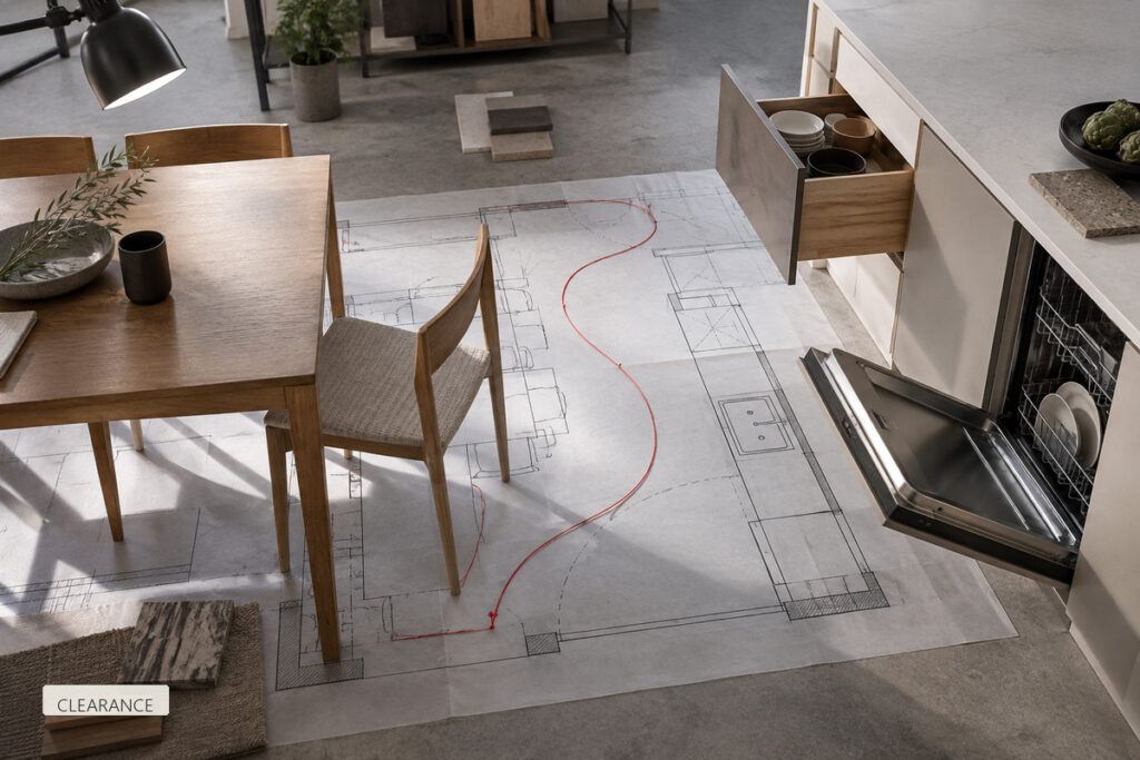
Test spatial conflicts with furniture and architectural openings simultaneously in use. A passage may seem wide enough until a swinging patio door, an extended recliner, or an open dishwasher door blocks the walkway. If the drawing lacks furniture blocks or shows generic undersized shapes, drafting a scaled furniture layout plan exposes these functional pinches before committing to custom production orders.
Trace Daily Movement Through the Home
Mentally walking the floor plan reveals functional bottlenecks that static room measurements conceal. Testing lifestyle circulation requires evaluating two distinct layers: active travel paths through shared work zones, and visual privacy across room transitions.
Primary Circulation and Work Zones
Trace daily routines from the primary entrance inward, following paths for dropping coats, carrying groceries, and moving between bedrooms and living spaces. In an open-concept kitchen and living room, active circulation frequently cuts directly between the prep island and lounge seating, making dedicated perimeter travel lanes necessary to avoid disturbing seated guests or cooks at work.
Sightlines and Room Adjacencies
Evaluate visual privacy and functional adjacencies at every doorway. Front entry vestibules should screen views into private bedroom corridors, while kitchen zones require direct service access to dining areas and outdoor terraces. Testing these spatial relationships ensures everyday comfort across the entire residential interior design scheme, keeping high-traffic routes efficient while insulating quiet retreats.
Prepare the Missing Information Before 3D Design
Translating an architectural drawing into a workable 3D model requires combining the floor plan with verified field conditions. Mark known discrepancies and altered openings directly on the latest revision of the plan. Pair the marked drawing with targeted residential design references to convey your preferred finish palette and spatial mood, then assemble these essential site details:
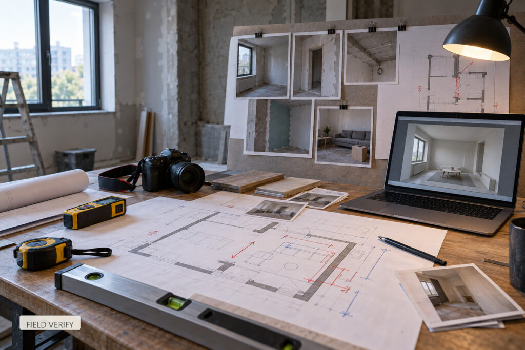
- Confirmed room dimensions and clear ceiling heights.
- Door and window openings, sill heights, and swing directions.
- Site photos covering every wall, corner, and ceiling condition.
- Property location, current construction stage, and room scope.
- Dimensions and photos of existing furniture to retain.
- Household storage priorities, daily routines, and budget guidelines.
- Known drawing discrepancies and unverified on-site conditions.
This documentation package provides design teams with the physical context required to verify whether a space is ready for 3D modeling or requires further field verification. It prevents costly redesigns caused by relying on outdated drawings or unrecorded field alterations.
At George Design Studio, we review the floor plan, measurements, site photos, project location, and room scope before recommending the next step. For qualified whole-home projects, our work can continue from 3D interior design into real-product selection and custom production coordination. Approved cabinetry, furniture, finishes, and selected project products can then move into specification, quotation, production review, quality checks, packing, and delivery planning within the agreed project scope.
Frequently Asked Questions
Can a Floor Plan Tell You Which Walls Are Load-Bearing?
No. While architectural plans use heavier line weights or double lines for thicker assemblies, these symbols indicate cut planes, plumbing chases, or exterior envelopes rather than structural capacity. Only structural drawings, framing plans, or an on-site evaluation by a licensed structural engineer or architect can verify whether a wall carries structural loads.
Is an Existing Floor Plan Enough to Start Interior Design?
An existing plan works for preliminary spatial review, but detailed interior design requires on-site verification. As-built field conditions often diverge from original drawings due to past renovations, shifted partition locations, or unrecorded plumbing bulkheads. Accurate design development requires confirmed field measurements, ceiling heights, window sill elevations, and comprehensive site photos.
What Should You Do If Floor Plan Dimensions Conflict?
Mark the discrepancy on the drawing and measure the physical space directly before ordering materials or finalizing joinery. Dimension strings occasionally clash when cumulative partition measurements do not match overall building dimensions. Designers should record verified as-built dimensions with the measurement date, update the drawing set, and resolve any downstream layout impacts immediately.